aside in favor of a stronger, prettier and much younger one.
We had to come up with a method of lifting the body tub
up high enough to remove the old frame. It had to be stable
and capable of lowering the tub back down with some
precision.
The rear tub lift jacks:

We had to be able to lift both the front and the rear of the
tub at the same time safely and up to a distance of about
28 inches. This would allow the frame to be easily rolled
out on furniture movers. Lifting the rear was easy once
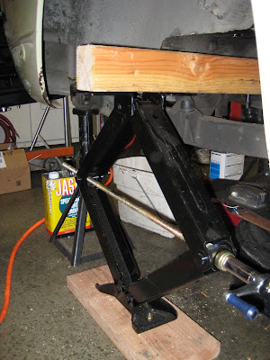
we discovered RV scissors jacks, sort of a scissor jack onsteroids. These jacks are capable lifting to about 32 inches,
more than enough. The bottom of the jacks were bolted to
2x6 planks for more stability and a 4x4 beam was cut to
length.

After removing basically everything from the frame,
including of course, the differential and half shafts there's
more than enough room to slide the 4x4 beam between the
front and rear diff bridge. A piece a 3/4 inch plywood was
used as padding to clear the seam of the inner fender.
Once the jacks and beam were in place the beam was
bolted to the top of the jack on each side.
The tub lift bar:
We had noted that there were two brackets with large
(about1.25 inch) holes in them, one on either side of the
engine bay just above and the towards the rear of the inner
fender. We surmised that these must have been used by
the factory to lift the body when the car was originally
assembled.

A closer shot of the drivers side lift hole. It was our evil plan
to use these holes to once again lift the front of the tub using
an engine hoist. But first, a lift bar would have to be
fabricated...

Two end brackets were fabricated from some scrap
3/8 inch aluminum plate and a 1.375 inch hole was
bored in each. Spacers were made from 1018 steel and
finally a T-nut was fashioned from some bar stock and
nut plate.

A closer shot of the spacer. The step in the center was
machined to just fit in the lift bracket hole. The bolt is
there to keep the T-nut from spinning when the end
brackets are tightened.

A close up the T-nut. A 3/8 bolt (NAS 6206) was inserted
through the end bracket and spacer into the T-nut after
it had been wrangled into the lift bracket hole. This was
no easy feat!

Once the end brackets were installed the lift bar itself was
slid into the holes bored in the end brackets. The lift bar
was made from 4130 seamless chrome moly tubing 1.375
diameter.
A shot of the bar being installed.

The lift bar is installed here. It also serves as a temporary
reinforcement for the engine compartment.

Collars were used to ensure that there was no lateral
movement.

Two hoist rings were installed to better balance the load.
A load leveler was also used with the engine hoist.
The forward lift jacks:

The forward lift jacks were basically the same as the rears
with the exception of the padding, 4x4's were needed to
clear the sills. The tub would rest on the beam at the very
forward most (strongest) section of the foot well.

A shot from the front. Obviously the forward lift jacks
could not be installed with the body still sitting on the
frame. Once the tub was lifted high enough off the frame
using the rear lift jacks and lift bar/engine hoist, the beam
could be slid in between the frame and tub. It was then
bolted to the top of each jack. The frame could then be
removed. More on that later...


No comments:
Post a Comment