Monday, December 28, 2009

Frame Removal April 08


We had all of the tub lift implements in place and
the RATCO frame was nearing completion. It was time
to remove the original frame. Although it had served
well (with a few notable exceptions) for almost 40
years, it simply had to go.


The front and rear lifting jacks are in place, the lift bar is ready to go and the engine hoist and load leveler have been positioned and hooked up.


A close shot of the lifting bar shows how it was attached to the engine hoist. Note the really cool swiveling hoist rings (1000 pound capacity!). Each of the hoist rings were chained to the load leveler, which was in turn attached to the hoist via yet another hoist ring, this one rated at 4000 pounds!


A better shot of the load leveler. The leveler allowed us to control the lateral attitude of the front of the tub.


The tub has parted company with the frame for the first time since it was first set on it all those decades ago.


 Kind of a cool shot low and from the rear. You can see how the lifting jacks were used to control the rear lateral attitude, a bad attitude right now. The jacks had to be raised in unison, one person on each side cranking a jack. Front and rear had to be kept fairly even also. All in all it worked really very well and we were both quite pleased with ourselves.


The idea was to raise the tub just high enough so that the diff bridge would clear the beam of the front lifting jacks. This shot shows the very rear of the frame, that's the spare tire compartment and part of the rear diff mount visible in the lower left corner.


Before the frame could be moved the front lifting jacks had to be put in place. Once the tub was raised high enough, the 4x4 beam and spacer pieces were slid in and lag bolted to the top of the jacks. With the weight taken off of the engine hoist, it could now be removed. The frame which been been sitting on four jack stands was carefully lowered onto a pair of furniture movers and it was finally freed at last!


A view of the center of the frame, the top T-shirt can be seen here. This frame was dirty but had very little rust.


You can see how high the tub had to be lifted to clear the diff bridge here, about 28 inches if I remember right.


A tight shot of the trailing arm member. Note the rust spot at the corner of the overlapped piece. The tub must have been rubbing here, the padding sitting on top is a joke!


A shot of the front diff bridge. The small holes are from a previous project to correct the horribly designed diff mounts, the passenger side mount was cracked on this frame.


What a relief, the job is done, well almost we still had to figure out what to do with the old frame before the new one came. By the way, you can make out some of our fleet in the background My TR-3 covered, the back of my Miata and just visible the rear of my partners X1/9. Not visible are her SAAB 9000 and Lancia Scorpion.


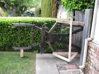
A triangulated wooden frame was fabricated out 2x4's and some casters. You can see the rear caster mounted on a 4x4 post lag bolted to the frame.


The fit had to be precise if the frame was to make it to it's new home!


A better shot of the main support frame.


The pole on the right is an old antenna mast, we just barely cleared!  The front caster is on the bottom of another short piece of 4x4. The old frame is now resting peacefully in the side yard, nicely oiled up and under a tarp.

Tuesday, December 15, 2009

The Tub Lift Project March 08

The time was nearing when the old frame was to be cast
aside in favor of a stronger, prettier and much younger one.
We had to come up with a method of lifting the body tub
up high enough to remove the old frame. It had to be stable
and capable of lowering the tub back down with some
precision.


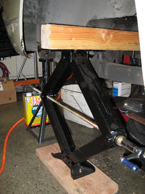
The rear tub lift jacks:


We had to be able to lift both the front and the rear of the
tub at the same time safely and up to a distance of about
28 inches. This would allow the frame to be easily rolled
out on furniture movers. Lifting the rear was easy once
we discovered RV scissors jacks, sort of a scissor jack on
steroids. These jacks are capable lifting to about 32 inches,
more than enough. The bottom of the jacks were bolted to
2x6 planks for more stability and a 4x4 beam was cut to
length.


After removing basically everything from the frame,
including of course, the differential and  half shafts there's
more than enough room to slide the 4x4 beam between the
front and rear diff bridge. A piece a 3/4 inch plywood was
used as padding to clear the seam of the inner fender.
Once the jacks and beam were in place the beam was
bolted to the top of the jack on each side.


The tub lift bar:


We had noted that there were two brackets with large
(about1.25 inch) holes in them, one on either side of the
engine bay just above and the towards the rear of the inner
fender. We surmised that these must have been used by
the factory to lift the body when the car was originally
assembled.


A closer shot of the drivers side lift hole. It was our evil plan
to use these holes to once again lift the front of the tub using
an engine hoist. But first, a lift bar would have to be
fabricated...


Two end brackets were fabricated from some scrap
3/8 inch aluminum plate and a 1.375 inch hole was
bored in each. Spacers were made from 1018 steel and
finally a T-nut was fashioned from some bar stock and
nut plate.


A closer shot of the spacer. The step in the center was
machined to just fit in the lift bracket hole. The bolt is
there to keep the T-nut from spinning when the end
brackets are tightened.


A close up the T-nut. A 3/8 bolt (NAS 6206) was inserted
through the end bracket and spacer into the T-nut after
it had been wrangled into the lift bracket hole. This was
no easy feat!


Once the end brackets were installed the lift bar itself was
slid into the holes bored in the end brackets. The lift bar
was made from 4130 seamless chrome moly tubing 1.375
diameter.


A shot of the bar being installed.


The lift bar is installed here. It also serves as a temporary
reinforcement for the engine compartment.


Collars were used to ensure that there was no lateral
movement.


Two hoist rings were installed to better balance the load.
A load leveler was also used with the engine hoist.


The forward lift jacks: 

The forward lift jacks were basically the same as the rears
with the exception of the padding, 4x4's were needed to
clear the sills. The tub would rest on the beam at the very
forward most (strongest) section of the foot well.


A shot from the front. Obviously the forward lift jacks
could not be installed with the body still sitting on the
frame. Once the tub was lifted high enough off the frame
using the rear lift jacks and lift bar/engine hoist, the beam
could be slid in between the frame and tub. It was then
bolted to the top of each jack. The frame could then be
removed. More on that later...

Monday, December 14, 2009

Body Mount Mod Engine Bay March 08

We found another design problem where the body mounts to
the frame in the engine compartment.


The some of the spot welds on reinforcement plate had
broken which lead to cracks in the body.


A shot of a crack emanating from a spot weld fatigue
failure. A hole was drilled to stop any further migration
of the crack.


It was decided to reinforce the reinforcement plate. First a
jig was made of cardboard, then the two above plates were
fabricated using .10 inch thick 4130 chrome moly (yes it is
overkill). The one on top already has a 90 degree bend at
the top. This increases the rigidity markedly.


The reinforcement bracket treated with rust killer after
carefully removing as much of the rust and debris from
underneath it as possible. The small hole center picture
was intended to be a drain hole, it didn't. The hole went
only through the plate, not the body. The larger hole just
to the right is the lone body mount bolt hole. My TR-3 has
two bolt holes here, a much stronger design as stress is
spread over a much larger area.


The reinforcement plate going in. The first hole is already
drilled and a cleco installed, the right way to do this job.


A second hole was drilled at the other end and another
cleco installed. Now the rest of these holes could be drilled.
Note the drill being used, an Atlas Copco right angle air drill.
Very power but easy to get into tight spaces. This is just one
of a huge assortment of air tools collected by my partner.


All of the holes have now been drilled in the original
reinforcement plate and the new piece. Since they were
both drilled together all the holes will line up perfectly
and are tightly toleranced.


Since several of the spot welds attaching the reinforcement
plate to the body had failed, it had to be firmly re-attached.
We decided to use an aircraft technique: carefully
toleranced holes, the correct hardware and lots of it. The
hardware used was 1) NAS 6703-3 #10-32, 3/16" grip. This
is a structural bolt made from A-286 stainless steel, cadium
plated. Minimum 160K psi tensile, 95K psi shear.
2) MS21042, a flange nut or jet nut. 3) AU 960 washer. If
this seems a tad bit hardware wonkish, that's because it is!
It is, however, all critical to getting a permanent repair.
The grip length is very important, it must such that the
shank of the bolt passes just through both pieces. This
ensures that each joint is "pinned", these joints will never
get loose and are stronger than a spot weld.


Another shot, we made certain that all of the body panels
were well connected!


A shot from the inner fender side.


A final shot, it's finally done! Although we did end up
turning some of the bolts around. I know some people will
look at this and shake their heads, massive overkill! But
this repair made a huge difference in the stiffness of the
area and was well worth the time and effort.


Buffer Area Painting March, May 08

I primed the buffer area at the same time as the interior and
boot. The seam sealing and top coat were applied at same
time as the engine compartment.


The passenger side buffer area and lower inner wing
(fender) after a coat of rust killer was brushed on.


A shot of the drivers side.


Same area after two coats of primer were brushed on.


A closer shot showing the lower rear inner wing area.
The hole just to the left of center was originally used
to access the cartridge oil filter mounting bolt.


The passenger side after priming.


Again, a close up of the passenger side lower rear wing.
Note the area above the triangular and square panels
was also cleared and refinished. Removing the old
undercoat was extremely difficult and dirty for me, so I
treated those areas that had become loose. This was
mostly because of oil soaking.


At this time, I also primed the area along the top of the
inner wing, where the outer wing mates.


This is the very front of the inner wing where it attaches
to the front valence. At some point before I owned the
car it was hit here, you can still see some wrinkles in the
metal work.


Some time later in May, I seam sealed the buffer areas
Along with the engine bay.


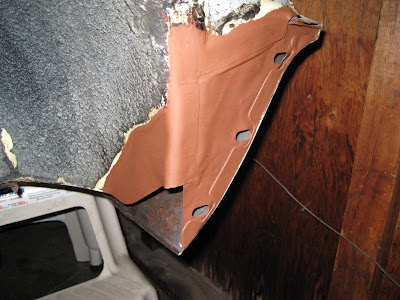
A shot of the corner that had the rust issues.


The lower rear inner wing panels, now seam sealed.
Note the 4x4 timber, this is part of the frame removal
process, more on that later.


The drivers side sill and the problem corner area.


The upper section of the buffer area.


The driver side lower rear inner wing showing the end
cap of the sill.


This, for some reason is the only picture I could find
of the buffer after the top coat. This was sprayed on
along with the engine bay. I followed up later with a
thick coat of a rubberized undercoat.