Friday, September 24, 2010

Diff Bridge Prep and Painting August 08

On my continuing saga to refinish the underside or the belly, if you like, of this beast I attacked the diff bridge area. This was the last remaining section and wasn't all that bad except that I had to work around the 4x4 beam and piece of plywood that was supporting the rear of the body. Basically I cleaned the front section first using simple green and a whole lot of elbow grease. I then lightly sanded the area going after any rust and there was virtually none. I used the same Permatex rust killer as before followed by a coat of primer and finally a top coat. I wasn't after aesthetics here just wanted good coverage and I knew that the whole thing would be finished off the a nice thick coat of spray on 3M rock guard undercoat.


Here's a look at the before condition. Not too bad, a lot of dirt and some oil slung up from a leaky diff.


This is how it looked after the initial cleaning, again not bad just a tiny bit of surface rust in a couple of spots.


A wider shot showing the entire area, a little bit of surface rust can be seen just at the bottom left of the drive shaft tunnel.


This is after treatment with the rust killer. There was some rust on the body mount bracket.


Another shot after the rust treatment showing the drive shaft tunnel. There was some rust all the way around the opening of the tunnel too.


Here I am beginning to apply the primer coat after a light scuffing with a scotch bright pad. All of the coats were brushed on, the point was good coverage.


The center shot again, after 2 coats of red lead primer.


This shot shows the left side after the first top coat.


And here the center shot once more. After I was finished here and the paint had plenty time to dry, I moved the support beam to the front area of the diff bridge and finished the rear section of the diff bridge using the same procedure. So was completed the dirty work, all that remained was to spray on the final under coat.

Wednesday, September 15, 2010

Rear Axle Mock Up July 08

We had gotten a Nissan R200 diff and I had cleaned it up and polished the rear mounting plate. I think it came out pretty cool, but now we had to fabricate some half shafts as the original u-jointed specimens simply would not do. We started with a pair of Good Parts CV conversion half-shafts. These were designed to fit the stock diff, which was the original plan, but things had obviously changed. The half-shafts we got were among the first batch made and had so some issues. But the new rear hubs were well done and a massive improvement over the stock hubs. It was decided to simply purchase a used set of Nissan half-shafts and use the inner CV joint and shaft cut down to the proper length and re-splined to fit the outer CV joint from the Good Part set.


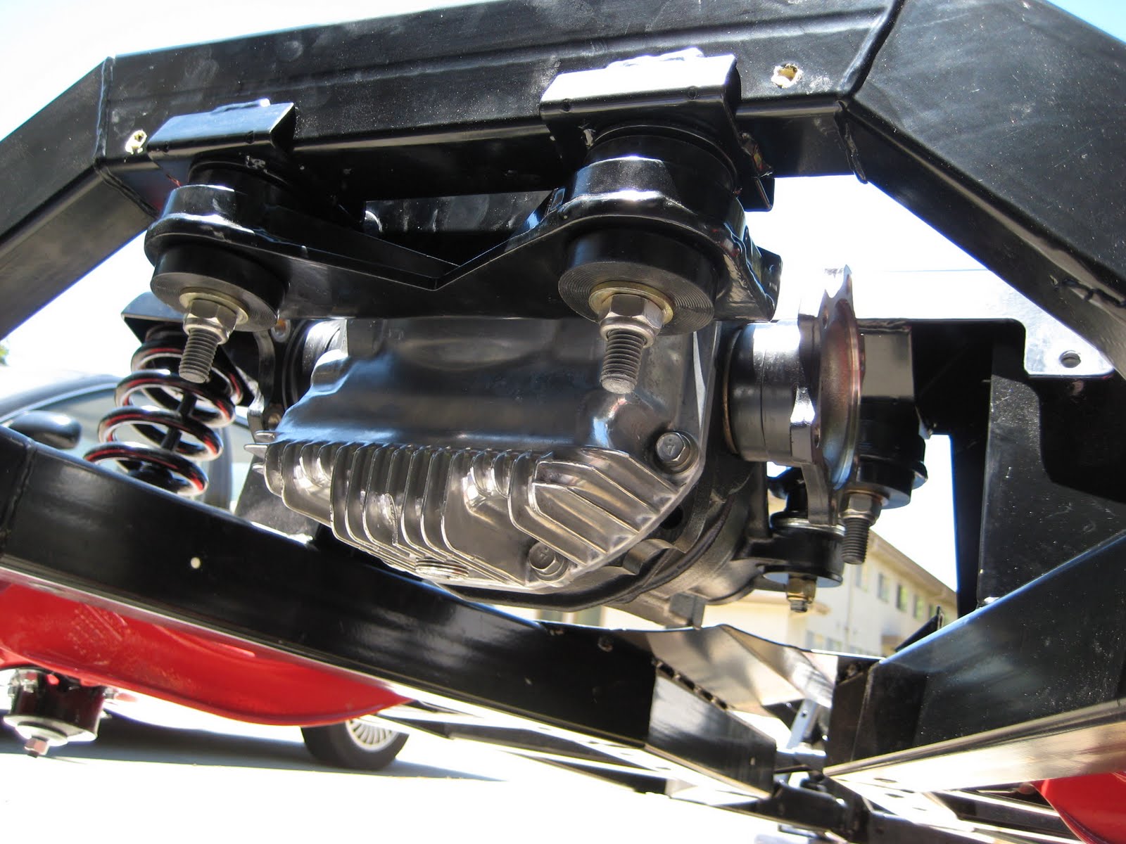
Here you see the Nissan diff sitting in it's new home, doesn't it look pretty?


A tighter shot showing the cooling fins, I spent a long time polishing that thing!


In this shot you can see, on the upper left, the flange of the inner CV joint being installed.


Here's a better picture of the inner CV joint install.


This is a view from the top, you can clearly see the left inner CV joint housing. That little tube with the tape on it left of center is the diff vent.


This shot gives a better view of just how massively built the CV joint housing is, ours has a 6 bolt pattern, a 5 bolt pattern is also available.


In this shot you can see that both inner CV joints have been installed as well as the new hubs and outer CV joint assembly's. That light brown stuff in between the inner and outer CV joints is just what it looks like, wood!


A tighter shot of the left side. The wood, or dowels actually, were used to simulate the shafts in order to find the proper length. A lot of care was taken to get an accurate measurement, the dowels were turned on a lathe to fit precisely into the inner assembly's of the inner and outer CV joints.


You can see from this angle that the measurements were taken with the trailing arms set to a neutral or level position. We also made sure that there was no binding throughout the range of movement of the trailing arm.


I included this picture even though it is a little blurry, to show just how tight the fit is between the outer CV joint and the inside of the trailing arm tunnel. We had to do some grinding to clear powder coat and irregularities in the casting.


 After we were happy with the final measurements of the dowels the Nissan shafts were rough cut using a cut off wheel. The shafts were then turned in a lathe to clean up the cuts and set the outside diameter to match the inside diameter of the outer CV joint. This was no easy task as the shafts were well hardened!! The shafts were then sent to Moser Engineering to have new splines cut.

Thursday, September 9, 2010

Miata Seat Mock Up June 08

So one day we started talking about the seats in the TR-6 for one reason or another. And how really pitiful it was that they were mounted with just 4 1/4'" bolts per seat? Really? And how since the nuts were welded on to the floor boards that the inevitable cracks had appeared around 3 of the 8, 2 on the drivers side. After much consideration and hair pulling, it was decided to jettison the old seats in favor of some nice Miata seats, which I am familiar with since I also own a '96. The problem was finding the earlier seats that have the back that narrows at the top. We couldn't find any that didn't need re-upholstery, so we ended up with a set from a 2007 Miata. These seats had never actually been farted into or used, as it were, since they were from a bunch of Miata's that had been modified for a race drivers school. They fit, but only just, and  installing them became one of the most difficult projects of all!


Now this is actually my partners X1/9, we bought 2 pairs of the seats and put a set her car first. I put this shot in here because it's the only decent picture of the seat!


OK, so here's the TR-6, the seats are just sitting on some pieces of wood to approximate their actual height.


Here's a view of the pair, I think they look quite nice but there is no margin for error between the seat shoulder and the convertible top pivot point.


I stuck one the original seats in there for just for comparisons sake. There is none, the original has virtually no head and neck support. The Miata seats will be far superior in the event of a rear end hit.


Same thing, different angle. The Miata seats are sooo much more comfortable! Cloth, lumbar support, I just wish that they narrowed more at the top of the seat back.


This picture shows the angle that the seat back takes right at the top. I like it and it really does seem to work with the lines of the car when viewed from the side.


You can see the side bolsters in this shot.


In this final shot you can see how broad the shoulders of this seat are, this caused me a lot of concern but in the end I think they will fit and be a huge improvement!

Thursday, September 2, 2010

Nissan Diff Mount Mock Up May 08

The original plan was to use the entire stock TR-6 power train with the exception of an upgrade to an Over Drive transmission. So much for plans. First, since it was discovered in October of 2007 that someone was offering a CV Joint half shaft conversion, I just had to have it. Then I was convinced that a Nissan R200 LSD differential ought to be included also.


So this is the Nissan Diff (as used in early 90's Q45) we bought for about $200 including shipping. It's built so much better than than the original that it would be difficult for me to articulate all of the differences here. Suffice to say that it's worth the money, and it comes with LSD!!


In order to fit the Nissan Diff to the frame it was necessary to first buy an adapter from Goodparts. Which seemed to work fairly well, at least at first. If I had to do this all again, I would have asked Ratco to build the mount into the frame.


In this shot you can see the rear mount, a very robust affair indeed.


Here is a view of the front mount. This one had some room for improvement...


A small protruding piece in the diff housing that had to be cut off in order in fit properly under the diff bridge.


A tighter shot, we ended up removing all of that bump and smoothing everything out.


Definitely a tight fit and we also have the rear anti roll bar which is routed up and over the diff to be concerned about.


It's a bit dirty right now, but when I get this thing all cleaned and polished it will look fantastic!