The RATCO Frame Build:

All the main sections of the frame layed out on
the jig.

A closer shot of the "T-Shirt" area of the frame. Welding
has begun.

Almost all welded nuts were eliminated in favor of the much
more versatale aircraft nut plates. Tack welded on in this
case, more normally a flush mounted rivet is used so no
welding at is needed. Welding a nut to sheet metal always
causes some weakness to both the nut and the surrounding
sheet metal.
Extra gusseting was added to the differential bridge tower.

Another shot of work in progress. Note now carefully the
frame is aligned before welding.

This is a shot of the front end showing the how the turrets
are aligned. Obviously accuracy is crucial here.

The basic frame has been welded. The upper "T-Shirt"
plate can be seen here. The lower T-Shirt plate is not
welded but rather bolted on to allow easier access to
the exhaust system.

A shot showing the underside of the diff bridge and the
front diff mounts, always a problem area with the TR-6
frame. Can you say poorly designed? Note the added
structure. The roughly horizontal pieces were added
to the stock mount forming a kind of pyramid structure
that is much stronger than the original, especially to
lateral forces. Note also the mongo diff mount pins.
These are M16, grade 12.9 socket head cap screws that
were cut off and welded in place.
The front end suspension, this is one of the lower A-arm
mounting brackets. These are notorious for failing on the
TR-6 frame. I should know, the rear mount on both sides
failed on my original frame. Not a pleasant feeling when
you hear metal ripping as you back out of your parking
spot! The two pieces extending at angles from the mount
are custom to this frame and strengthen the area even
more.

Same area as above viewed from the back. You can also
see here that the motor mount has been tied into the lower
A-arm bracket.

A shot of the front end with all four A-arm brackets installed.

The frame is nearly completed here.

This is a shot of the front lower A-arm bracket and the
steering rack mount. Note that it is also tied in to the
bracket for more strength and another vulnerable area.

Another frontal shot.

The front lower A-arm mount again, the welding completed.
Pretty impressive and very solid looking, a vast improvement
over the stock frame.

The whole frame, now very close to completion.

We decided to add a jacking plate at each corner, it's
just visible here.

The frame got put on a scale, don't remember how much
it weighed!
Back from powder coating and lookin' so fine!
The front looks so pretty in black!
This shot shows just how good that black and red look
together. Its also shows the rear suspension modification.
The elbow arm damper is tossed and a tubular damper
is placed inside the coil spring. The former damper
mounting hole at the end of the trailing arm is now used
by the anti-roll bar link. Note also the adjustable trailing
arm brackets.
Another shot of the trailing arm from the
front this time. The adjustable trailing arm
brackets now in clear view.
The complete and ready to go.
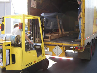
Time to crate it up for the long, long trip from New York
state to California.
And into the truck it goes. The trip was not without it's
bumps in the road! More about that later...


